Serial Peripheral Interface
Publish date: Sep 13, 2019
Last updated: Apr 22, 2020
Last updated: Apr 22, 2020
IMAGE GALLERY (1)
- Official Documentation12
- a multiplexed shift register32
- 74HC595
- Shift register and Storage register3
- 4 clock cycles to transfer 4 bit message
- Range 1-20 MHz
- The Raspberry Pi is equipped with one SPI bus that has 2 chip selects.
CPHASE=1 data is sample d at trailing edge of clock
We want to use 3 slaves with SPI0, but am335x supports only 2 CS signals.
Device tree configuration for SPI Polarity and Phase
		spi-cpol;
		spi-cpha;
From /proc
/proc/device-tree/ocp/spi@48030000

root@beaglebone-yocto:/sys/firmware/devicetree/base/ocp/l4_wkup@44c00000/scm@210000/pinmux@800/spi0_pins_default# pwd
/sys/firmware/devicetree/base/ocp/l4_wkup@44c00000/scm@210000/pinmux@800/spi0_pins_default
root@beaglebone-yocto:/sys/firmware/devicetree/base/ocp/l4_wkup@44c00000/scm@210000/pinmux@800/spi0_pins_default# ls -la
total 0
drwxr-xr-x  2 root root  0 Oct 22 14:29 .
drwxr-xr-x 21 root root  0 Oct 22 14:29 ..
-r--r--r--  1 root root 18 Oct 22 14:42 name
-r--r--r--  1 root root  4 Oct 22 14:30 phandle
-r--r--r--  1 root root 40 Oct 22 14:29 pinctrl-single,pins
root@beaglebone-yocto:/sys/firmware/devicetree/base/ocp/l4_wkup@44c00000/scm@210000/pinmux@800/spi0_pins_default#

mount /dev/mmcblk1p1 /mnt
find . -type f -exec head {} + | less
- Binary file 2.
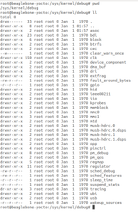
Using debugfs
/sys/kernel/debug/sys/kernel/debug/pinctrl/44e10800.pinmux-pinctrl-single/pingroups- RAM-based file system specially designed for debugging purposes
# check if trace is enabled
cat /proc/sys/kernel/ftrace_enabled

# pins associated with spi
cat /sys/kernel/debug/pinctrl/44e10800.pinmux-pinctrl-single/pingroups | grep -A5 -i spi
From dtb file
- Open Core Protocol (OCP)-based architectures
OCP is a standards-based embedded-bus interface and multicore IP integration protocol defined by the OCP-IP industry consortium
DTFL=/mnt/am335x-boneblack.dtb
fdtget $DTFL --list /
fdtget $DTFL --properties /
fdtget $DTFL --list /cpus
fdtget $DTFL --list /ocp     # buses
fdtget $DTFL --properties /ocp/spi@48030000
fdtget $DTFL /ocp/spi@48030000 --type s status

for i in $PROPS; do out=$(fdtget --type x $DTFL spi0 $i); echo -e "$i\t\t$out";  done

fdtput $DTFL --verbose --delete /ocp/spi@48030000 status
fdtput $DTFL --verbose --remove /ocp/spi@48030000 status
fdtput $DTFL --verbose --create /ocp/spi@48030000 status okay
fdtput $DTFL --verbose --type s /ocp/spi@48030000 compatible rohm,dh2228fv
Testing
watch --interval 1 --differences 'DTFL=/mnt/am335x-boneblack.dtb; PROPS=$(fdtget $DTFL --properties /ocp/spi@48030000); for i in $PROPS; do out=$(fdtget $DTFL /ocp/spi@48030000 $i); echo -e "$i\t\t$out"; done'
Sample output fdtdump $DTFL --scan | grep -A15 'spi@48030000 {'
spi@48030000 {
    compatible = "rohm,dh2228fv";
    status = "okay";
    #address-cells = <0x00000001>;
    #size-cells = <0x00000000>;
    reg = <0x48030000 0x00000400>;
    interrupts = <0x00000041>;
    ti,spi-num-cs = <0x00000002>;
    ti,hwmods = "spi0";
    dmas = <0x00000027 0x00000010 0x00000000 0x00000027 0x00000011 0x00000000 0x00000027 0x00000012 0x00000000 0x00000027 0x00000013 0x00000000>;
    dma-names = "tx0", "rx0", "tx1", "rx1";
};
- ti,spi-num-cs
- Number of chipselect supported by the instance.
&spi0{
    pinctrl-names = "default";
	pinctrl-0 = <&spi0_pins_default>;
    status = "okay";
    #address-cells=<1>;
    #size-cells=<0>;

    spidev@0{
        compatible="spidev";
        reg =<0>; //chipselect 0
        spi-max-frequency= <3125000>;
    };
    spidev@1{
        compatible="spidev";
        reg =<1>; //chipselect 1
        spi-max-frequency= <3125000>;
    };
    spidev@2{
        compatible="spidev";
        reg =<2>; //chipselect 2`
        spi-max-frequency= <3125000>;
    };

imu@X {
     compatible = "adi,adis16480";
     reg = <YOUR_CHIPELECT_PIN_NR>;
     spi-cpol;
     spi-cpha;
     spi-max-frequency = <1000000>;
};
- Driver to use for this device
- Register where device could be found
- Control device state, on/off
- SPI frequency breakpoints 1Mhz, 2MHz, 3.2mHx
./spidev_test -v
spidev_test --device /dev/spidev0.0 --verbose -p 'MESSGAE' --speed 250000

# Write binary 1, 2 and 3
echo -ne "\x01\x02\x03" > /dev/spidev0.0
spi0_d0 as MOSI. I just change on kernel & u-boot mux data but it seems not enough
ti,pindir-d0-out-d1-in: Select theD0pin as output andD1as input.- The default is D0 as input and D1 as output.

